¶ General
The Scenario Manager essentially lists all the content (symbols, background plans, etc.) contained in a plan document.
The Scenario Manager is structured like a classic tree structure, which can be expanded or collapsed at any time by clicking on  .
.
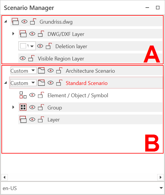
The tree structure is divided into two main areas. Area (A) displays the imported background plans (floor plans), and expanding it provides access to the DWG, DXF, and PDF layers. Area (B) contains the planning content.
The following elements/objects can appear or be created in the Scenario Manager:
| Scenario: Scenarios are separate drawing areas. Each scenario displays only the existing content and cannot be displayed simultaneously with other scenarios, except for the Architectural Scenario. The Architectural Scenario only exists if walls or objects from the RED CAD APP's Architectural Scenario have been drawn. By default, a scenario called Default Scenario exists. Additional scenarios can be created by right-clicking on the Default Scenario → New Scenario. |
|
| Schema/Circuit Diagram Page: Single page in a schematic/circuit diagram document. In addition to the page number, additional information about the page content can be displayed. |
|
| Object/Symbol/Graphic: Basically all objects that are placed in a document by the user. |
|
| Group: Grouped objects. The contents of a group can vary and are created by the user. |
|
| Layer: Background plan layers or layers created by the user. |
|
| BKP Layer: Only visible if a BKP (construction cost plan) structure has been created. A standardized BKP structure can be created by right-clicking in the Scenario Manager and can also be expanded by the user. |
|
| Areas: (from left to right) Object structure OGL, Position Location PSL, Facility Type ET. This structure is derived from NPK (Standard Position Catalog). Visible when using the area structure [Link]. |
Control functions that have elements/objects:
| Show/Hide: Objects, layers, scenarios, etc. can be hidden and shown again using this control to generate a better overview or views. The objects are not deleted, but merely made invisible or visible. |
|
| Lock/Unlock Objects, layers, scenarios, etc. can be locked and unlocked using this control. Locking objects prevents accidental changes. The object must be unlocked again to make changes. |
|
| Show/Hide Existing Layers: These controls only exist within a Steiger project. Layers that exist throughout the entire project can thus be displayed, even if the layers may not have been created in the current document. This prevents layers from being created twice within a Steiger project. |
The Scenario Manager offers options for structuring a document, such as creating a layer structure, forming groups of elements, and making changes to the imported background plan.
¶ Functions
¶ Creating new scenarios
If, for example, the planning should be divided into two independent areas, it is recommended to create two or more scenarios.
Scenarios cannot be combined. Each scenario displays only its content and hides all other scenarios.
Create a new scenario
- Open the Scenario Manager
- Right-click on the default scenario
- Select New Scenario
- A new scenario is created
¶ Renaming Scenarios
Assigning a unique name to a scenario makes it easier to navigate in the Scenario Manager and the parts list.
Renaming a scenario:
- Open the Scenario Manager
- Double-click the scenario name → The name will now be displayed in a text field
- Change the name
- Click Enter
- The name will be applied
¶ Selecting the Structure Type
For a scenario, the structure type can be defined using the dropdown menu on the left. Depending on the selection, the content within the scenario is automatically sorted and listed.
The following structure types can be selected.
| Custom | Standard structure type. The objects/symbols are all listed individually and chronologically. Furthermore, only in this structure type can a custom layer structure be created. |
| Category | The objects/symbols are grouped together according to their toolbox category. |
| Norm | The objects and symbols are grouped together according to their unique symbol ID. |
| Name | The objects/symbols are grouped together according to their name. |
| Area | The objects/symbols are grouped according to the area they are located in. |
| SIA | The objects/symbols are grouped according to the SIA standard. Used in conjunction with the NPK tool from Eit.Swiss. |
¶ Renaming Objects
The default name for objects (e.g., symbols) can be changed at any time.
Changing the name can be helpful for the parts list and the legend, because two identical objects with different names are listed separately.
Renaming Objects:
- Open the Scenario Manager
- Double-click the object → The name will now be displayed in a text field
- Change the name
- Confirm with Enter
¶ Creating/Ungrouping Groups
You can group symbols, text boxes, and other objects. Groups allow you to move, rotate, and so on multiple objects simultaneously as if they were a single object.
The keyboard shortcut to create a group is Ctrl + G. To ungroup, use Ctrl + U.
Creating Groups:
- Open the Scenario Manager
- Hold down the Ctrl key while clicking on the objects you want to group.
- Once all objects are selected, right-click an already selected object.
- Select Group
- The group is created.
Dissolving groups:
- Open the Scenario Manager
- Right-click on the group
- Select Dissolve group
- The group is dissolved
¶ Creating your own layers (layer structure)
If you want to organize your planning by function, purpose, or rooms, it is recommended to create your own layer structure.
The custom layer structure can also be helpful for structuring the parts list.
Custom layers can only be created if the structure type for the scenario is set to Any
Creating your own layers:
- Open the Scenario Manager
- Right-click on the standard scenario and select New Layer → Layer is created
- Assign a name to the layer
You can also nest layers by performing step 2 on an existing layer.
¶ Generating the BKP Structure
If you want to plan according to the BKP (Construction Cost Planning) structure, you can load the standard BKP structure. The BKP structure can be customized at any time and expanded to include non-existent positions (layers).
Structure must be loaded before planning
Load standard BKP structure:
- Open the Scenario Manager
- Right-click on the standard scenario and select New BKP Layer Structure → Structure is loaded and standard layers are created
¶ Expanding the BKP Structure
Expand the BKP Structure (Add BKP Layer):
- Open the Scenario Manager
- Right-click on the layer where you want to add the new layer
- Select New BKP Layer
- In the window, select a predefined layer from the list or create a completely new BKP layer using the input fields below
- Then click OK → BKP Layer is added
¶ Adding Objects to a Layer (BKP Layer)
For self-created layers, the objects (symbols, elements, etc.) are not automatically placed in the corresponding layer by the RED CAD APP when they are placed. This must be done manually and controlled by you.
As long as no other layer is selected via the Scenario Manager, the layer remains active and all objects are placed within it.
Add objects to the layer:
- Open the Scenario Manager
- Click the layer to which you want to add the objects → Layer name is displayed in bold
- Select the corresponding object and place it in the planning
- The object appears in the layer
¶ Moving objects within a layer (BKP layer)
Objects can be moved at any time within a layer structure or BKP structure.
Moving objects/groups to the layer (via drag & drop):
- Open the Scenario Manager
- Left-click the corresponding object and release the button
- Drag the object to the corresponding layer
- Release the left mouse button
- The object is moved to the layer
Moving objects/groups to the layer (via cut & paste):
- Open the Scenario Manager
- Left-click the corresponding object
- Press the key combination Ctrl + X → Object is cut
- Click the corresponding layer to which the object is to be moved
- Press the key combination Ctrl + V → Object is pasted
If multiple objects are to be moved simultaneously To move the objects, click them one after the other while holding down the Ctrl/Strg key.
¶ Showing/Hiding Background Plans
Imported background plans (floor plans) can be shown or hidden at any time.
This does not permanently delete the background plans, but merely removes them visually from the drawing area!
Showing/Hiding Background Plans:
- Open the Scenario Manager
- The background floor plans are located at the top of the scenario manager
- Click on the eye icon to the left of the floor plan file name
- The background plan appears or disappears.
¶ Accessing the Background Plan Layers
Architects/planners often organize their plans according to purpose, function, or similar criteria, and this is achieved by creating layers.
These layers are, in turn, readable by most CAD systems, and users can adapt the plan to their needs by hiding the corresponding layers.
In addition, hiding layers can reduce the complexity of the plan while improving display performance.
Access the layer structure and show/hide layers:
- Open the Scenario Manager
- The background floor plans are located at the top of the scenario manager
- Click on the corresponding floor plan file on the left side,
- Click on the DWG/DXF layer or PDF layer on the left side, → The floor plan layer structure is displayed
- Find the layer you want to show/hide and click on the eye icon
- The layer appears or disappears.
¶ Deleting Background Plans
Imported background plans that are no longer needed can be permanently removed from the document.
Delete/remove a background plan from the document:
- Open the Scenario Manager
- The background floor plans are located at the top of the scenario manager
- Right-click the background plan file you want to delete
- Select Delete Background Plan
- Confirm the action with OK
- The background plan is deleted from the document