¶ The simple CAD
The RED CAD APP is a very simple and intuitive CAD software for the electrical, plumbing/heating, and maintenance industries.
You can find more detailed explanations on all topics in our wiki.
¶ Program view
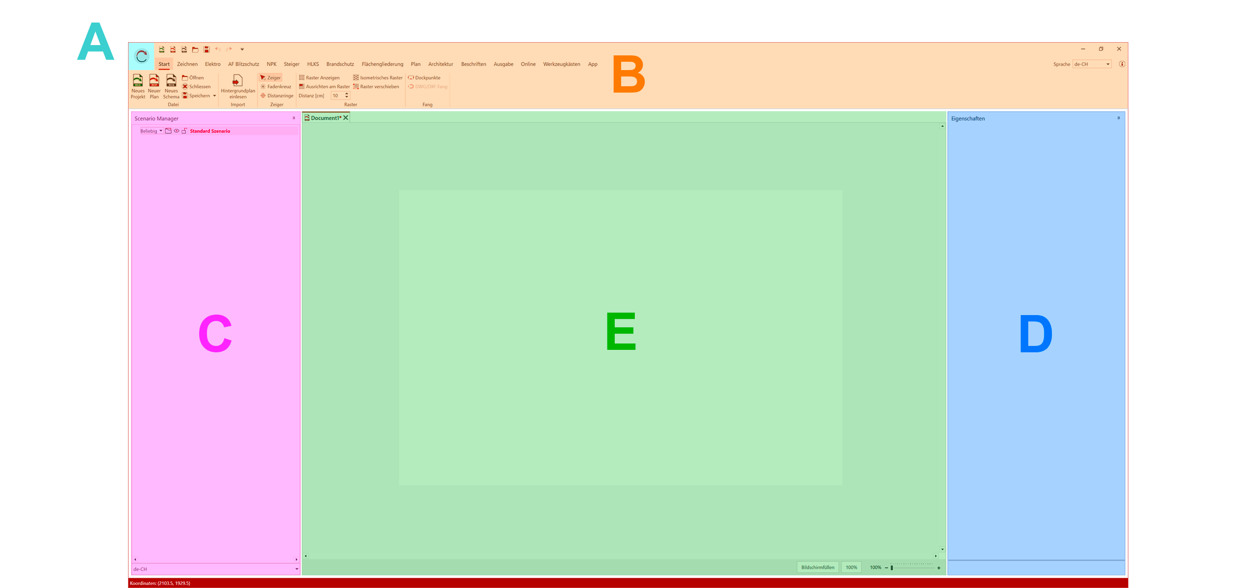
(A) Main Menu - (B) Ribbon including Quick Access Toolbar - (C) Scenario Manager - (D) Properties - (E) Artboard/Workspace
¶ Main Menu
The main menu can be opened via the RED CAD logo (top left).
It contains, for example, the program settings, the document settings, the license information, and much more.
A complete explanation of the main menu can be found under Main Menu
¶ Ribbon
The Ribbon (A) is the main navigation of the RED CAD APP. It contains the main menu, the tabs for accessing the various functions, and the quick access bar.
¶ Scenario Manager
In the Scenario Manager (B), all objects such as placed symbols, imported background plans, and created pages (for schematics/circuit diagrams) are displayed and listed.
A complete explanation of the Scenario Manager can be found at Scenario Manager
¶ Workspace/Artboard
The Workspace/Artboard (C) is the view in which the document is planned and drawn.
Project management is also displayed here.
¶ Properties
The Properties (D) display the setting options for the selected elements/objects.
A complete explanation of the properties can be found under Properties
¶ Mouse and keyboard commands
A complete overview of available mouse and keyboard commands can be found under Mouse and keyboard commands
¶ Documents/Projects
New documents/projects can be created in the Home tab, in the Main Menu, or in the Quick Access Toolbar using the corresponding buttons.
¶ Create a document (plan/schematic)
Plan Document:
- Open the Home tab
- Click the New Plan button
- The plan document is created and opened
Schematic/Circuit Diagram Document:
-
Open the Home tab
-
Click the New Plan button
-
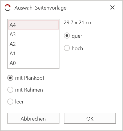
Define your page template in the dialog that appears
-
Confirm the page template by clicking OK
-
The schematic/circuit diagram document is created and opened
¶ Creating project files
When working with project files, only the documents contained within a project file can be opened and edited.
- Go to the Start tab
- Click on the New Project button
- Select the desired project type
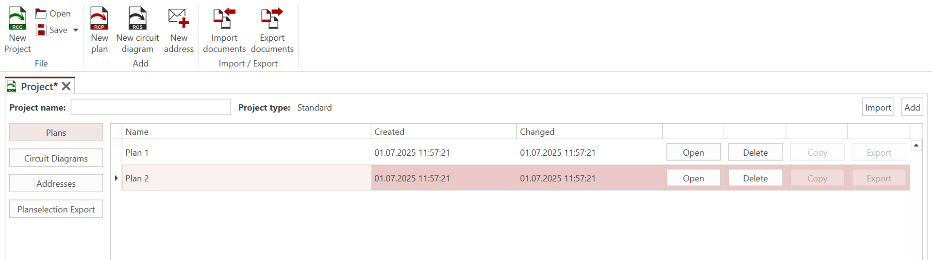
- Project Management opens

-
The plan and schematic/circuit diagram documents are then added or created within Project Management using the New Plan or New Schematic buttons.
-
The document name is defined in the Name column.
-
Click the Open button (to the right of the document name) to open the document and start planning.
¶ Opening Documents/Projects
Existing documents/projects can be opened via the Start tab → Open / Main menu → Open or directly from Windows Explorer by double-clicking.
¶ Saving Documents/Projects
Documents/project files can be saved via the Start tab → Save (or Save As) or via the floppy disk icon in the Quick Access Toolbar.
The keyboard shortcut for saving is Ctrl + S
¶ Background Plan
In the RED CAD app, floor plans in DWG, DXF, and PDF file formats can be imported as background plans.
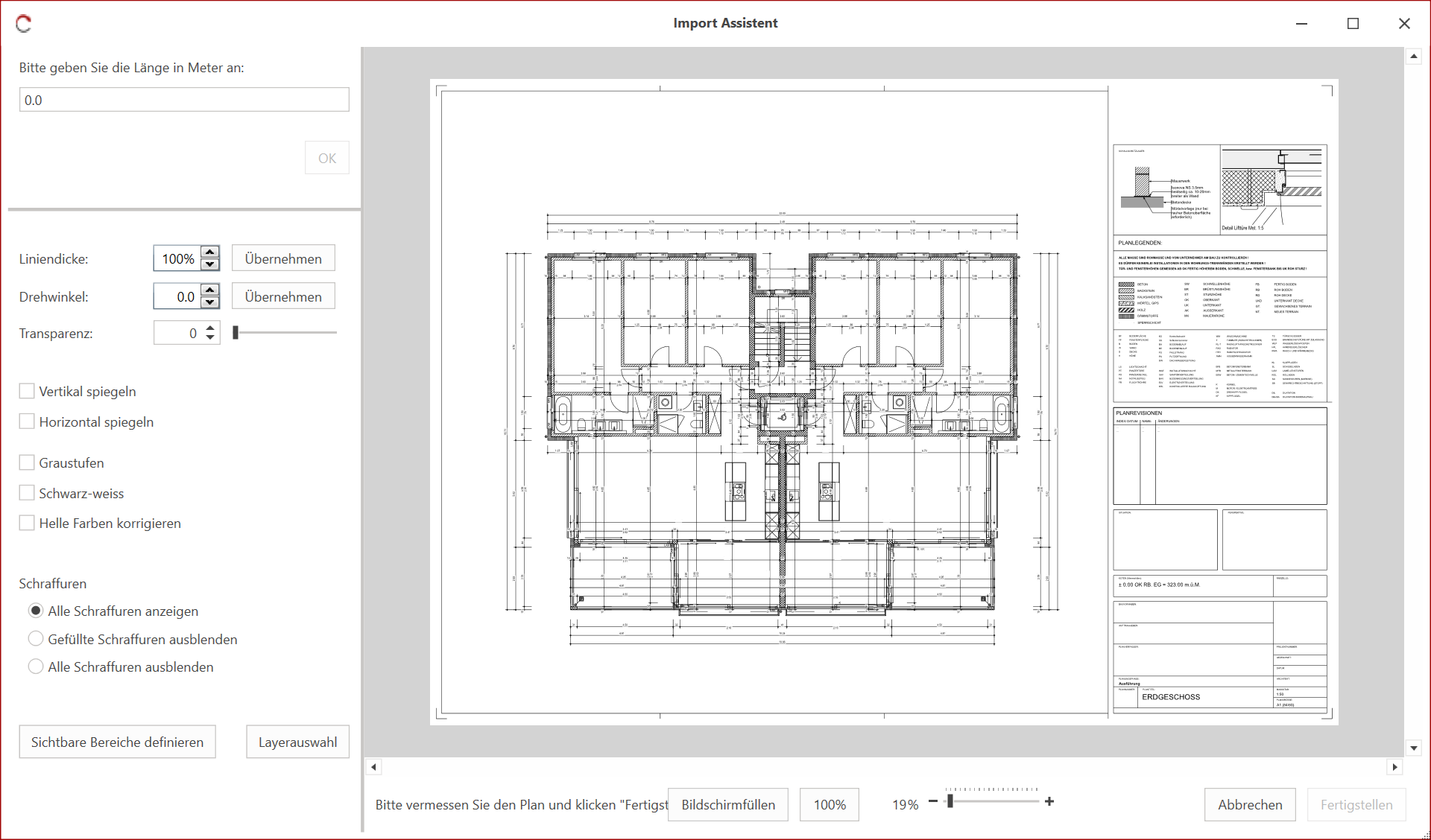
The import is performed using the Import Assistant, which is primarily used to measure the background plan. The assistant also offers the option of customizing the plan, such as changing the color, appearance, showing or hiding layers, etc.
Further information on importing background plans and the Import Assistant can be found under Import Assistant
¶ Importing a background plan
The import process remains unchanged regardless of the file format. For DWG and DXF files, you also have the option to customize the line thickness.
- An empty document must exist or an existing document must be open to import a background plan.
- Multiple floor plans can be imported into one plan document.
- The reference distance value must always be entered in meters.
-
Open the Home tab.
-
Click the Import Background Plan button.
-
Select the background plan file in Windows Explorer and click Open.
-
The Import Assistant opens.
-
Go to a known line (e.g., a dimension line) and draw the arrow for the reference line (start ←→ end) with two left-clicks.
-
Enter the length of the reference line in the input field in the top left (in meters).
-
Confirm your entry by clicking OK or pressing Enter.
(More information about the correction tool) -
(Optional) Adjust the background plan to your needs using the display options.
-
Click Finish in the bottom right corner to complete the import process.
-
The Import Wizard closes and the background plan is imported.
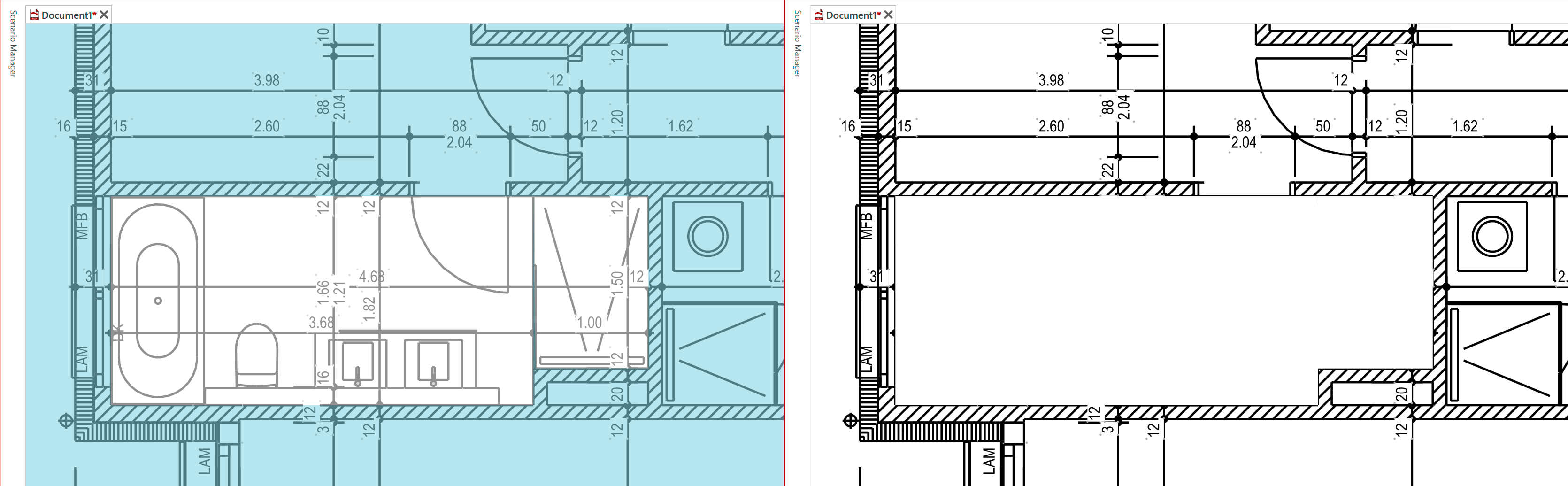
¶ Erase Layer
The Erase Layer function allows you to cover any area in the background plan, thereby creating an open space.
The function can be found in the Plan tab and can be activated using the Erase Layer button.
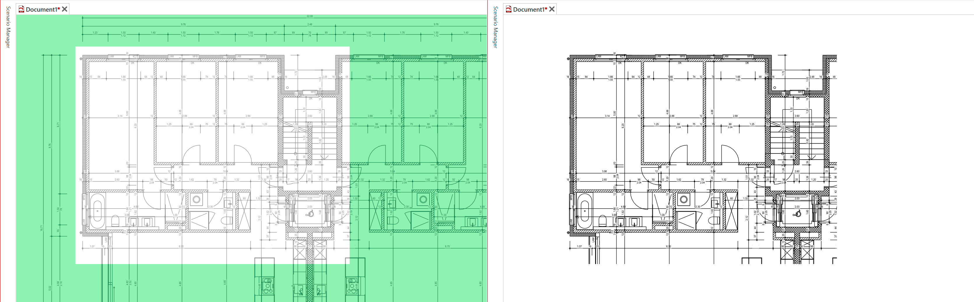
¶ Visible Area
The Visible Area function allows you to limit the imported background plan to a specific area.
The function can be found in the Plan tab and can be activated using the Visible Area button.
¶ Symbols (Toolboxes)
The RED CAD app's standard symbol library is located under the Toolboxes tab. Additional partner symbols can be found in the APP tab.
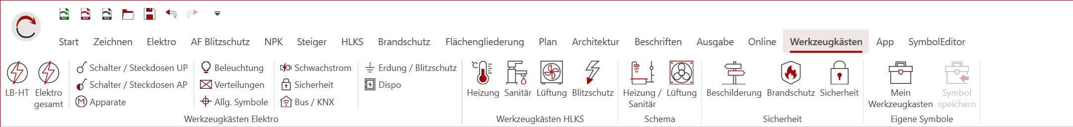
¶ Opening a Toolbox
A toolbox is opened by left-clicking on the corresponding library and is displayed in a panel/window.
¶ Placing Symbols
- Select the symbol in the toolbox by left-clicking.
- Move the mouse to the desired position where you want to place the symbol and left-click.
- The symbol is placed.
As long as no other symbol is selected via the toolbox, the selected symbol remains active. This means you can place the same symbol in other positions by repeating step 2.
To place other symbols, select a new symbol in the toolbox and repeat the process.
¶ Labeling Symbols
All symbols have invisible text fields that can be displayed and then labeled.
Red text field = No content
Green text field = Has content
- Go to the symbol you want to label.
- Double-click the symbol with the left mouse button.
- The text fields will be displayed in red.
- Double-click the corresponding text field with the left mouse button.
- The Properties window will open and display the input field.
- Enter the desired text in the input field.
- Double-click the symbol with the left mouse button.
- The text fields will be hidden.
The text fields can alternatively be shown/hidden with the L key if the symbol was previously selected with the left mouse button
¶ Lines & Piping
The functions for Lines, Piping, Ducts, etc. are located in the tab for your specific department, e.g., Electrical, HVAC, Fire Protection, etc.
Important:
The Line or Curve drawing functions from the Draw tab should not be used for planning lines/piping. Length information will not be visible in the parts list. Therefore, lines and piping must always be drawn using the designated function.
¶ Appearance (Basic Settings)
The appearance of a line, piping, duct, etc. is defined in the Department tab. These settings then serve as the default settings for future lines, pipes, and ducts.
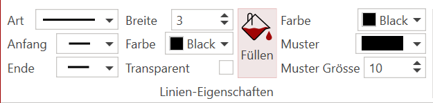
Already drawn lines can be adjusted at any time via the Properties window.
¶ Draw lines/piping
The way lines, piping, etc. are drawn basically always works the same way.
- In the corresponding tab (Electrical, HVAC, etc.), select the desired drawing type, e.g., AP line, with a left click.
- Move the mouse to the starting point of your line and left click to set the starting point.
- Move the mouse and the line is drawn.
Each additional left click sets a new point to change the direction of the line.
-
When you reach the end point of the line, double-click with the left mouse button.
-
The line is closed.
Alternatively, the line can also be closed with the Enter key.
¶ Labeling (text field, title block legend)
The RED CAD APP offers various labeling options. In addition to text fields, it also offers predefined elements such as legend, two different title blocks, equipment positions (1+2), and a revision cloud.
All functions can be found in the Labeling tab
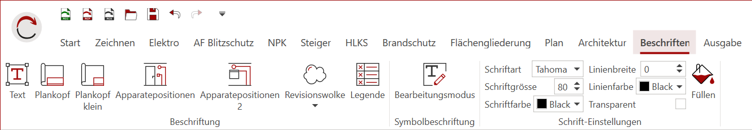
¶ Font Settings
The default font settings, such as font size, font type, font color, etc., can be found to the right of the label functions and can be defined there.
Text fields can be adjusted subsequently and at any time via the Properties window.
¶ Create a text field
- Select the Text function with a left click.
- Move the mouse to the desired position for your text field.
- While holding down the left mouse button, drag the text field to any size and release the left mouse button.
- The text field is created and the Properties window opens automatically.
- Now enter your desired text in the focused input field.
Alternatively, the text field can be placed in the desired position with a left click. With this option, the text field is created in a standard size and must be enlarged later.
¶ Placing and Filling Out the Title Block
There are two different standard title blocks available in the RED CAD APP: a detailed title block and a simple title block.
- Select the desired title block by left-clicking
- Move the mouse to the desired position for the title block
- Place the title block by left-clicking
- Open the Properties Window
- All input fields are displayed
- Enter your desired text in the corresponding input fields
The contents of a title block are saved by the RED CAD APP, meaning the most recent entries are loaded into a new plan. This means the content only needs to be adapted to the new plan and does not need to be redefined.
¶ Create Legend
The legend lists all symbols used in the plan. If a previously unused symbol is subsequently added to the plan, the legend must be updated by generating/setting a new legend.
- Select Legend with left-click
- Move the mouse to the desired position for the legend
- Place the legend with left-click
The symbol name can be changed in the legend if necessary by double-clicking on the corresponding symbol name. However, if the legend is reset, this information will be lost.
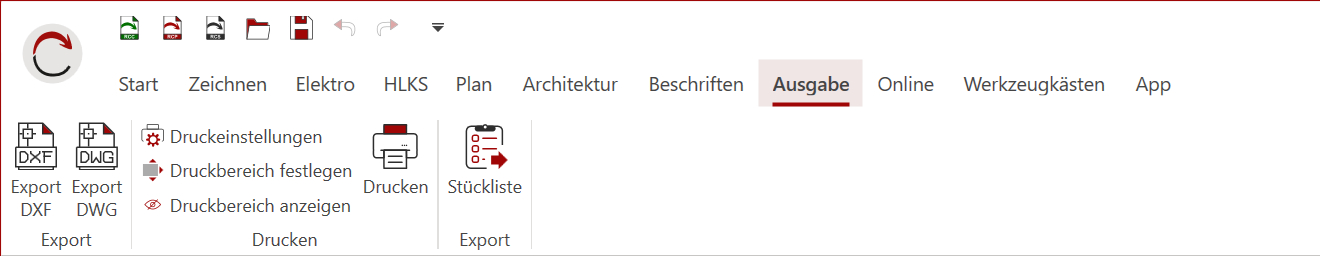
¶ Output/Export
All plans created in the RED CAD APP can be exported as DWG, DXF, and PDF files.
The export functions are located in the Output tab
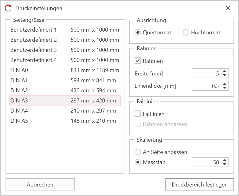
¶ PDF (Print)
By default, the RED CAD APP always creates a PDF file and does not trigger a physical paper print. Paper printing is performed via the installed PDF software.
-
Go to the Output tab
-
Click Print Settings
-
Print Settings / Print dialog opens
-
Define your page according to the available settings
-
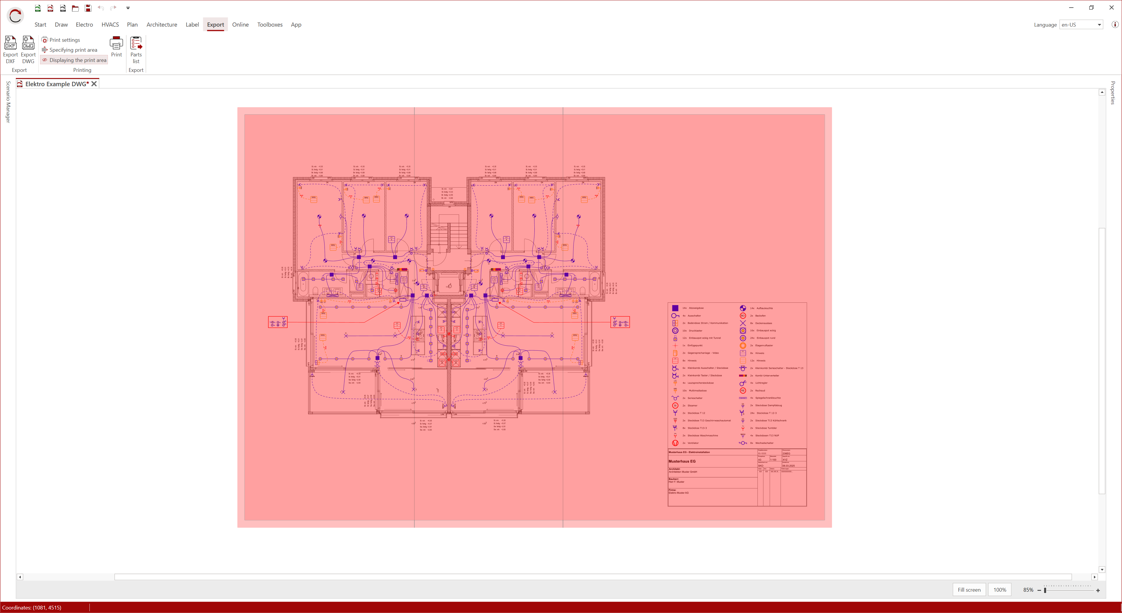
Click Set Print Area to generate the print area
-
Position the print area (red area) and confirm the position with left-click
-
Click the Print button in the Output tab to start printing.
-
The PDF file will be created in the background, and your default PDF program will open after a few seconds.
-
Save the PDF file to your computer or Print the PDF file via your printer/plotter using the default program you use.
If the PDF file is closed without saving, the file will be discarded and must be recreated.
For a full explanation, see Print
¶ DWG/DXF
If the imported background plan is to be included in the export, the imported background plan must be either a DWG or DXF file. Otherwise, only the drawn objects and symbols will be exported.
The RED CAD APP is not able to convert a PDF file to a DWG/DXF file.
-
Select the desired function Export DWG / Export DWG by left-clicking.
→ The file format of the imported floor plan file determines which export function you must select. -
The DWG/DXF Export Settings dialog opens.
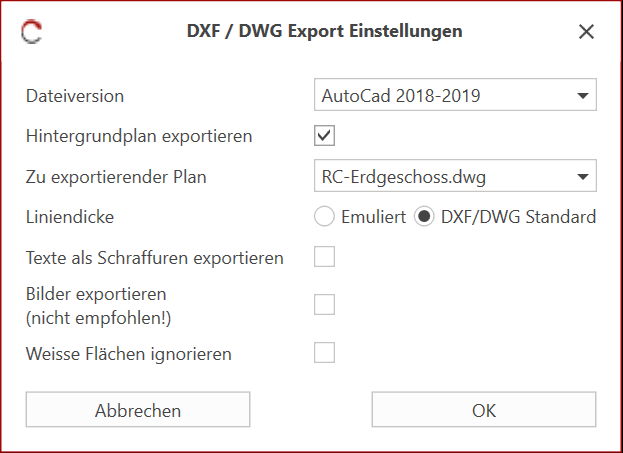
-
Define the export using the available settings.
-
Confirm the settings by left-clicking. OK
-
Windows Explorer will open
-
In Windows Explorer, select the desired save path for your export file
-
Enter a file name for your export file
-
Start the export process by left-clicking on Save
For a full explanation, see Export DWG/DXF